CM-Cabinets Library User Guide
Drawer Runner machining incorporates both the drilling of the ends (of divisions) with runner holes for the selected drawers, and also the drilling of the drawer box parts themselves.
The library uses external lookup tables which are referred to in the following discussion (for users that are familiar with tables). However it is important to note that CabMaster Software™ distributes most of the runner tables and allows customers' to tweak the choice, detail and machining data for drawer runners using the Runner Editor. These amendments are written to a separate override file, thereby preserving the original.
The name of the table containing the specification for drawer runner holes is located in the content of the RunnerHoles column of the applicable runner table. This runner hole table is assumed to be in the \Table\Machining\DrawerRunners folder. It contains a matching row for each row in the Drawer Runner Table i.e. -500mm, -400mm etc. For more information on these tables refer to Drawer Runner Groups Explained.
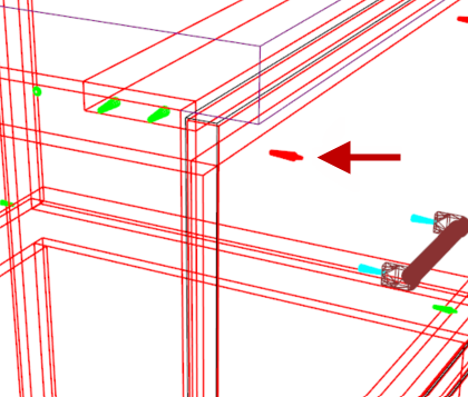
Drawer Runner Holes are drilled in the Ends or Divisions in which the drawer box sits.
An optional column Runner2Holes can be added to the runner table. This provides the ability to have an independent second set of runner holes for drawers. This primarily was to enable holes at two different depths for the same runner.
All runner tables have ability for up to 16 holes per runner (each of which can be offset vertically). This should allow for runners requiring two sets of holes (e.g. Harn Impaz Sylent*).
The Drawer Runner hole tooling default is located in the Mach. General >Tool page of the Catalog/Drawing properties.

Mach.General > Tool page - Click to Expand
Table Format of Runner Holes Explained - click to view
The format of Runner holes is a follows.
Rows
One row for each runner length stored as a negative number and listed in ascending order (this is the same concept as the Runner Tables).
Columns
|
VPOS |
There are the three (3) different methods used to calculate the vertical position of the drawer runner i.e. this can have a value of 'Bottom', 'Side' or 'Mid' If from the drawer 'Bottom' then the vertical height of the drawer runner is offset from the bottom face of the drawer box base. If 'Mid' then the vertical height of the drawer runner is offset from midway between the bottom and top of the drawer side. If from the drawer 'Side' then the vertical height of the drawer runner is offset from the top of the drawer side. The vertical position of the drawer base is calculated using the methods discussed below. The top of the side is based on this calculation and the height of the drawer side. |
|
VDIST |
The vertical offset from the VPOS position (+ve for upwards and -ve for downwards). |
|
1x...16x |
The horizontal offset to the centre for holes (max 16 holes supported). If zero, then no hole drilled. |
|
1y...16y |
Vertical offset from the vertical height of the runner to the centre of the holes. |
The TDiam and TDepth columns are optional and could appear in the tables referred to by the 1st and/or 2nd set of runner holes. If present as in the example below, they override the drawer runner hole tooling default in the drawing properties.
The layer name for the 1st set of runner holes is taken from the Layers table, shown above right, and the layer name for the 2nd set of runner hole is <runner>-2.
The positioning of the drawer base in relation to the drawer front can be calculated in two different ways.
Drawer Extra Holes are the holes drilled in the drawer box itself to hold it together.
The content of the ExtraHoles column in the drawer runner table is the name of the table containing the specification for these holes. This extra hole table is assumed to be in the \Table\Machining\DrawerRunners folder.
Sample of ExtraHoles table: StandardExtraHoles.qlt
If the content of the ExtraHoles column if this is blank or invalid, then no holes are drilled.
One Extra Hole table may be shared with several different Runner Tables. It is also possible that different rows within the same Runner table point to different Extra Hole tables.
Table Format of Extra Holes Explained - click to view
The format of the Extra Holes table is as follows.
|
BottomBack |
Connection of the drawer base (bottom) and drawer back. Whether these holes are in the back or base will depend on the construction type relationship between them (i.e. if screwed with the back above base then hole will be in the base otherwise the back). |
|
BottomSide |
Connection of the drawer base (bottom) and drawer sides. Whether the holes are in the side or base will depend on the drawer type and the construction method. |
|
BackSide |
Connection of the drawer back and drawer sides. Whether the holes are in the back or base will depend on the drawer type and the construction method. |
|
Type |
What type of construction is to be used. The value here is the same as used in the construction settings on the Mach.General > Construct page of the drawing/catalog. 1=screw, 2=cam, 3=nail and 4=other |
|
Qty |
The quantity of fixings required (minimum of 2). Zero (0) will use a minimum of two and then increase the number based on a maximum spacing as stated in the Space column. |
|
Dist |
The distance from the end of the part to the outside fixings. |
|
Space |
The maximum spacing of the fixings (only used if Qty column is 0) |
|
Layer |
This will be appended the content of the column to the default layer name used for the machine step used to connect these various drawer parts. For example, assuming the following…
Then the layer name used for the hole in the drawer Back for the Bottom would be “screw-3mm” |
Additional holes for the Back, Bottom (Base), Side, Front and Panel can be drilled in the back, base, front (internal) and/or the front panel of the drawer i.e. these are additional to the fixing of the drawer components together as described above.
The names of the tables containing the specification for these holes are located in the content of the BackHoles column, BottomHoles column, SideHoles column, FrontHoles and/or PanelHoles columns in the drawer runner table.
FrontHoles can also include donated matching holes in the front panel.
Example of donated matching holes
The runner configuration tables for the drawer box fronts can include holes that are transferred to the drawer front panel.
Click to view options
Tables are assumed to be in the \Table\Machining\DrawerRunners folder.
If this is blank or invalid, then no holes are drilled.
These tables may be shared with several different Runner tables. It is also possible that different rows within the same Runner table point to different tables.
Because these tables contain CabMaster formulas, it is wise that they are created and edited by a CabMaster consultant who understands the CabMaster formula and CM-Cabinets library structures.
Drawer components have a series of tables that define their machining. These are selected via the drawer runner tables as shown below.
Example: A table called Blum TandemBoxBottomHoles650.qlt is to be used for the drawer Bottom in a 650mm drawer of this type.
This table, which can contain up to 8 rows of information, will be located in the \Table\Machining\DrawerRunners\Blum Tandembox folder.
Table Format of Special Holes Explained - click to view
The format of the both the Back and Bottom Hole table are as follows.
Each table contains 8 rows (one for each set of possible holes) labelled 1, 2, 3, 4, 5, 6, 7, 8.
|
Name |
Detail |
Example - See Image below i.e. Example of Base Holes Table |
|
Use |
Whether to use or not. 1=Yes, 0=No |
1 = Yes |
|
Layer |
The machine layer name |
"BigHole" - Note that as this text field is not a formula it has single quotes around the double quotes. As a layer name this will need also to be defined in the EzyNest ATP. |
|
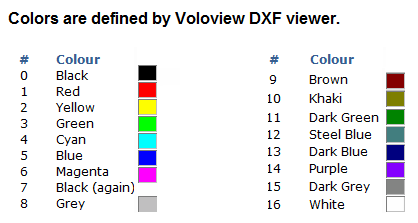
Colour |
The colour of the DXF layer (0 to 16) |
0 = Black (See DXF Colours) |
|
Diam |
The diameter of the hole |
22.5mm |
|
Depth |
The depth of the hole |
5mm - Note to drill all the way through use "Dim3" |
|
X |
Offset in the X direction # |
5mm |
|
Y |
Offset in the Y direction # |
57mm |
|
RepQty |
Repeat quantity |
2 |
|
RepX |
Repeat offset in the X direction |
"-center[1].x+(Dim2-57mm)" |
|
RepY |
Repeat offset in the Y direction |
0mm |
The origin for the offsets, except for the Front Panels, is the bottom left hand corner of the machined face of the finished part.
For the Front Panels the X origin is the inside edge of the cabinet end and the Y origin is the bottom face of the drawer base to which the front panel belongs.

The front panel (drawer fronts) can also have an additional 2 sets of holes (10 in total), plus up to 3 single line grooves (i.e. machined lines from A to B).
Table Format of Drawer Front Panels - click to view
The grooves are applied by adding additional rows to the table, with rows 1-10 defining holes and rows 11-13 defining the grooves as follows.
|
Name |
Detail |
|
Use |
Whether to use or not. 1=Yes, 0=No |
|
Layer |
The machine layer name |
|
Colour |
The colour of the DXF layer (0 to 16) |
|
Diam |
UNUSED for grooves |
|
Depth |
The depth of the groove |
|
X |
Start of groove in the x direction |
|
Y |
Start of groove in the y direction |
|
RepQty |
UNUSED for grooves |
|
RepX |
End of groove in the x direction |
|
RepY |
End of groove in the y direction |
&nbpsp;


